Thick concrete cannot be treated like a shallow slab: the cutting method must account for wire access, reinforcement, hidden services, water, structural movement and the weight of every separated block. By the end, you will know how to assess the section, plan the cut sequence and specify the controls that make wire sawing workable on deep concrete.
Key takeaways
- Confirm reinforcement, prestressing tendons, services and temporary supports before cutting.
- Use guide pulleys and controlled wire tension to maintain the planned cutting path.
- Control water flow, slurry collection, wire speed and tension throughout the cut.
- Sequence isolation, drilling, rigging, cutting, lifting and debris removal before starting.
How the diamond wire cuts through a deep concrete section
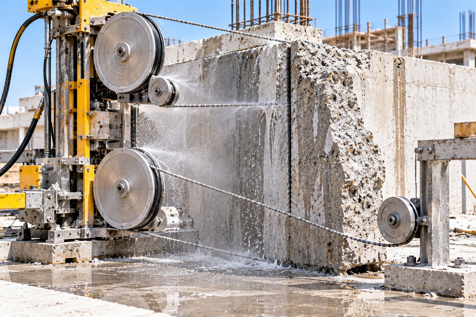
A drive wheel pulls a continuous diamond-embedded wire loop through the concrete. Diamond beads grind the section as the loop runs around guide pulleys and corner pulleys, while a tensioning system maintains contact and a controlled wire angle.
Continuous water cooling cools the beads and carries fines from the kerf, preventing heat and abrasive slurry from slowing the cut.
| Method | Practical limit | Result |
|---|---|---|
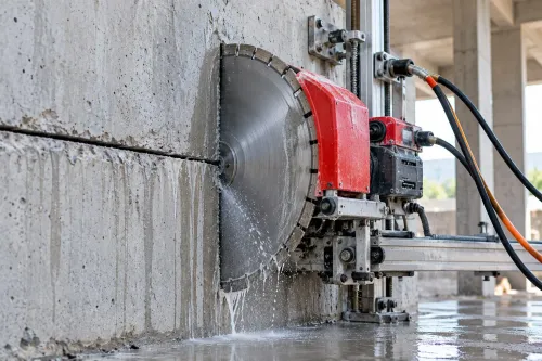
| Wall saw | Wall saw depth is constrained by blade radius and cutting depth | Effective for accessible faces, but a circular blade cannot pass through very thick sections in one operation |
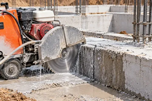
| Floor saw | Requires a rolling surface and straight access | Suits slabs, not vertical walls or irregular deep members |
| Handheld cut-off saw | Suited to shallow local cuts | Limited reach, alignment and operator control |
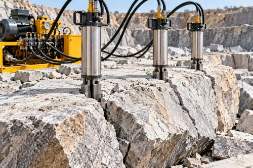
| Concrete breaker | Uses impact rather than a guided abrasive path | Creates vibration, debris and less controlled geometry |
Typical diamond beads measure about 10–11 mm in diameter, but the finished kerf width is wider because of bead geometry, cable movement and wear. Wire sawing suits foundations, dams and thick walls because the loop passes through drilled access holes and around the section.
Wire depth is governed mainly by access holes, loop length, pulley layout, machine capacity and removal of the cut mass—not by blade diameter. That geometry lets you divide a deep section into controlled cuts instead of forcing a circular blade beyond its reach.
What must be checked before choosing wire sawing
A thick section is suitable for wire sawing only after you prove that it can be cut, supported and removed without an uncontrolled movement. Record these points before selecting the method:
- Section thickness, concrete type, aggregate hardness, reinforcement congestion, rebar diameter and congestion.
- Access around cut, including access on both sides and available drilling positions.
- Desired cut geometry and the route for lifting, landing or removing each block.
| Check | Why it matters | Decision |
|---|---|---|
| Structural drawings and GPR scan | Locates reinforcement, ducts and voids, embedded services, prestressing tendons and post-tensioning cables | Stop if records conflict with scan results |
| Ducts and voids | A void reduces wire contact and cutting action; it can also change the load path and make movement occur earlier than expected | Probe, rescan or redesign the cut |
| Reinforcement | A trapped or severed bar can close the kerf, pinch the wire and cause breakout | Plan release cuts, lifting or restraint |
| Load-bearing function | Cutting can remove compression paths, sever reinforcement and destabilise the remaining structure | Obtain an engineer’s sequence and temporary works design |
Never assume a tendon is absent because it is not visible. Require the engineer to define propping, load paths, sequential cuts and the effect of removing a load-bearing member.
Keep a clearance or sacrificial breakout zone where the wire approaches waterproofing, bearings, finishes or cracked concrete. Low vibration does not prevent damage from pulley reactions, wire tension, block movement or local breakout at the cut’s end.
How a thick-section wire-sawing operation is sequenced
A thick section is cut as a planned sequence of releases and lifts, not as one unsupported monolith. The site survey establishes dimensions, access, hazards and the removal route; scanning then confirms reinforcement, ducts, voids and services before drilling.
1. Transfer the approved geometry to the concrete by marking the cut faces, entry points and lifting points. Check the marks against structural drawings, scanning results and the intended block size.
2. Drill accurately positioned wire-access holes through the section. Use corner drilling where one straight cutting path cannot reach the full geometry, and verify hole positions so the wire enters at the designed angle.
3. Complete wire threading and joining around the section. Carry out pulley installation at entries, exits and corners, then check that each pulley rotates freely and the wire tracks without rubbing concrete or forming a sharp bend.
4. Set wire tension to the manufacturer-specified value, confirm guards and exclusion zones, and start the water supply before engaging the drive. Operators watch wire tracking, kerf width, slurry discharge, bead condition and movement of the surrounding structure throughout the cut.
5. Make sequential cuts, using staged cuts and intermediate releases instead of leaving a large unsupported block. Plan wedges, jacks, secondary cuts or controlled lifting to release compression and stop the kerf pinching the wire when reinforcement closes it.
6. Calculate reinforced-concrete mass from volume and density: at 2.3–2.5 tonnes per cubic metre, a 0.5 m³ piece weighs roughly 1.2 tonnes before lifting effects. Confirm the lifting plan, then lower each released piece onto its planned landing area and remove it.
What controls cutting speed, wire wear and water on site
No reliable programme can use one metres-per-hour figure: cutting speed changes with aggregate hardness, cement-paste strength, concrete age, repair materials, reinforcement ratio, rebar diameter, wire specification, tension, wire speed and flushing. Wire wear, not motor power, often controls output in a thick section.
Steel is cut by the same diamond wire, but steel obstructions increase resistance and accelerate bead wear. A severed bar can close the kerf and trap the loop, so allow for reinforced-concrete wire selection, controlled tension and staged release of the cut.
Continuous water cooling protects the beads, flushes fines from the kerf and suppresses airborne respirable silica. In a thick section, insufficient delivery leaves abrasive slurry in the slot, reducing cutting speed, raising wire temperature and promoting premature wire failure; excessive water without drainage creates a slippery, contaminated site.
Use this site checklist:
- Install bunds around the cut and route slurry to dedicated slurry capture, not an open drain.
- Match water delivery to section depth, and provide drainage that cannot back up into the kerf.
- Use wet-vacuum extraction to collect slurry, protect nearby drains with covers or plugs, and apply runoff treatment before discharge.
- Remove dried residue before it becomes dust; wet cutting does not eliminate respirable silica exposure.
- Keep electrical equipment and cables outside wet paths where possible, provide electrical RCD protection, and restrict access to the slippery wet-work zone.
How to control structural and wire-sawing risks before the first cut
Low vibration does not make a load-bearing member safe to cut. Treat the work as a controlled package: cutting can remove compression paths, sever reinforcement, release stored tension and destabilise the remaining structure.
1. Issue a method statement and structural sequence before mobilisation. Confirm reinforcement, services and post-tensioning cable locations from GPR findings and drawings; record stressing details and post-tensioning safety controls before approving any release. Install temporary propping wherever the cut changes load paths.
2. Prepare a written lift plan for every block. State its calculated weight, verified lifting capacity, certified gear, landing area, lifting points and communication method. Reinforced concrete weighs about 2.3–2.5 tonnes per cubic metre, so a 0.5 m³ block is roughly 1.2 tonnes before lifting effects.
3. Mark a line-of-fire exclusion zone around the wire plane, pulleys, suspended loads and possible falling concrete blocks. Keep people out of line with the tensioned wire, use the manufacturer’s guards, and treat wire breakage as a recoil or whip hazard caused by stored tension.
4. Specify sequential cutting, movement monitoring, planned release of compression and emergency actions for wire failure, water ingress or instability. Do not let a pinched kerf force the wire to finish the cut; use jacks, wedges, secondary cuts or controlled lifting.
When appointing Salasar Demolitions Pvt Ltd, request the marked cut sequence, GPR findings, pulley layout, wire specification, slurry plan, RCD arrangements and lifting calculations. A claimed cutting rate is not a risk-control document.
Related products
 | CONCRETE CUTTING BY WIRE SAW MACHINE We offer complete, carefully thought-out, easy-to-use wire saw machine. View product → |
 | CONCRETE CUTTING BY DIAMOND SAWING by diamond wire sawing View product → |
Frequently asked questions
How does diamond wire saw cutting pass through thick concrete?
A drive wheel pulls a continuous diamond-embedded wire loop around guide and corner pulleys. Diamond beads grind through the concrete while the tensioning system maintains contact and a controlled wire angle.
What must you check before choosing wire sawing for a deep concrete section?
Check the section thickness, reinforcement, prestressing tendons, embedded services, access, drainage, lifting capacity, temporary supports and the required cut geometry.
How is a thick-section wire-sawing operation sequenced?
Plan isolation and support first, establish the cut line, install guide pulleys, create wire access holes, thread the loop, set tension, make the cut, lift the separated section and remove slurry and debris.
What controls wire-sawing speed, wire wear and cooling water?
Wire speed, tension, concrete hardness, aggregate type, reinforcement, cutting pressure and water flow control cutting progress, bead wear and heat. Collect slurry rather than allowing it to enter drains.
How can you control structural and wire-sawing risks before the first cut?
Verify the structural method, exclusion zone, temporary works, utility isolation, lifting plan, wire condition, pulley alignment, emergency stop and communication procedure before starting.